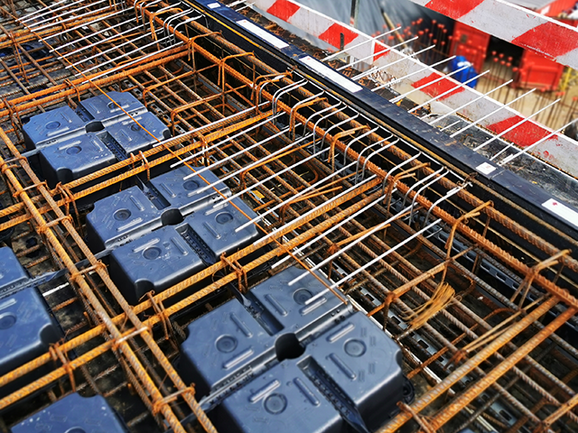
U-Boot® Beton is a recycled polypropylene formwork (Void box) that was designed to create lightened slabs and rafts.

The use of U-Boot® Beton formwork makes it possible to create mushroom pillars, with the possibility to have the mushroom in the thickness of the slab.

Thanks to the conic elevator foot, immerging the U-Boot® Beton formworks in the concrete casting will create a gridwork of mutually perpendicular beams closed from the bottom and the top by a flat plate that is created with a single casting; this results in considerable reduction in the use of concrete and steel.

U-Boot® Beton is used to create slabs with large span or that are able to support large loads without beams.
Light and quick and easy to position, thanks to their modularity the designer can vary the geometric parameters as needed to adapt to all situations with great architectural freedom.

REFERENCES

New Sports Centre

Tuscany - Italy
U-Boot® Beton

GHC Hotel in Caorle, Venice

Caorle (VE) - Italy
U-Boot® Beton

Shopping center

Nablus - Palestine
U-Boot® Beton

MTN Headquarters

Abidjan - Ivory Coast
U-Boot® Beton

Foundation raft of a poultry shed

Foggia - Italy
U-Boot® Beton

"Impiana Jaya Complex" Shopping center

Bandar Seri Begawan - Brunei
U-Boot® Beton

ADVANTAGES

Sistema ottimizzato con U-Boot® Beton

Traditional one way slab

System optimised with U-Boot® Beton

1. INCREASED NUMBER OF FLOORS
Possibility to gain floors at the same building height (towers) and building volume.

2. LACK OF RISING BEAMS
Flat soffit for greater flexibility when installing systems.

3. REDUCED SLAB THICKNESS
Thinner slabs but with equal loads and clearances, or bigger clearances with an equal thickness.

4. LARGE SPAN AND GREAT ARCHITECTURAL FREEDOM
Larger spaces. Less architectural restrictions. Freedom of future reconversion of the environments from an architectural-functional point of view.

5. FLEXIBILITY IN THE REALIZATION OF OPENINGS AFTER THE EXECUTION OF THE SLAB

6. REDUCTION IN THE NUMBER OF PILLARS
Facilitated use reallocation. Wider bays.

7. OPTIMISATION OF THE SECTION OF PILLARS

8. IMPROVED ACOUSTIC BEHAVIOUR
Less acoustic transmittance.

9. POSSIBILITY OF PASSING UTILITIES IN THE THICKNESS OF THE SLAB

10. POSSIBILITY TO USE IT WITH POST-TENSION

11. REDUCED FOUNDATIONS
Lower costs for foundation excavations. Less excavation.

12. REDUCTION IN THE OVERALL LOAD OF THE STRUCTURE WEIGHING ON THE PILLARS AND THE FOUNDATION.

Cheapness of two-way lightened voided slabs U-Boot® Beton system

We are incorrectly led to estimate the advantage of a slab lightened with U-Boot® Beton limiting it to a mere comparison between savings in concrete and the cost of the formwork on the level of the slabs only.
In this way however, as the analysis is immediate and intuitive, it does not account for the various economic, practical and operational advantages provided with U-Boot® Beton for the entire structure:
less use of iron in the slabs, pillars and foundation up to a total of 15% (also in the case of variants); less concrete is used not only for the slabs but also for the columns and foundations; there are antiseismic advantages connected to reduced building weight; slimmer pillars and foundations, lower costs related to excavation for foundations; the arrangement, also irregularly if needed, of the pillars to reflect the architectural freedom of the structure. Reduction of work and overhead transfer of the formworks; advantages in on-site logistics.

APPLICATIONS

U-Boot® Beton is a recycled polypropylene formwork that was designed to create two-way voided slabs and rafts. The use of U-Boot® Beton formwork makes it possible to create mushroom pillars, with the possibility to have the mushroom in the thickness of the slab.
Thanks to the conic elevator foot, immerging the U-Boot® Beton formworks in the concrete casting will create a gridwork of mutually perpendicular beams closed from the bottom and the top by a flat plate that is created with a single casting; this results in considerable reduction in the use of concrete and steel.

U-Boot® Beton is used to create slabs with large span or that are able to support large loads without beams.
Light and quick and easy to position, thanks to their modularity the designer can vary the geometric parameters as needed to adapt to all situations with great architectural freedom.

RAFTS

Among the various foundation types, rafts are one of the most well known. They are used above all in ground conditions with little bearing capacity, or with poor quality soil, large thicknesses must be used which increases the construction cost.
Thanks to the use of U-Boot® Beton lightened rafts can be created with the same performance but at a considerably lower cost.
Once drown in the concrete casting, U-Boot® Beton forms the structure just like two full slabs, with a variable thickness, connected by a perpendicular beam gridwork to form a bidirectional static honeycomb plate.

For this concrete bed, the distribution of weights due to hight inertia is rationalised in order to permit maximum stiffness and lightness for the structure with a minimum amount of concrete, which makes it possible to eliminate, where possible, the foundation piles.

TECHNICAL DATA

U-BOOT® BETON SINGLE

Height H
(cm)
Dimensions
(cm)
Foot height p
(cm)
Weight per piece
(kg)
Piece volume
(m3)
Pallet dimensions*
(cm)
Pallet pieces*
(pcs/PAL)
Pallet weight*
(kg/PAL)
H 10 cm 52 x 52 0-5-6-7-8-9-10 1,395 0,0213 110 x 110 x 247 720 1.107
H 13 cm 52 x 52 0-5-6-7-8-9-10 1,406 0,0280 110 x 110 x 212 600 857
H 16 cm 52 x 52 0-5-6-7-8-9-10 2,044 0,0350 110 x 110 x 254 440 912
H 18 cm 52 x 52 0-5-6-7-8-9-10-12 1,784 0,0396 110 x 110 x 249 440 798
H 20 cm 52 x 52 0-5-6-7-8-9-10 1,644 0,0430 110 x 110 x 236 460 769
H 22 cm 52 x 52 0-5-6-7-8-9-10-12 1,882 0,0470 110 x 110 x 253 440 841
H 24 cm 52 x 52 0-5-6-7-8-9-10-12 2,033 0,0513 110 x 110 x 254 440 908
H 25 cm 52 x 52 0-5-6-7-8-9-10 1,849 0,0518 110 x 110 x 249 440 827
H 26 cm 52 x 52 0-5-6-7-8-9-10-12 2,044 0,0550 110 x 110 x 249 420 871
H 28 cm 52 x 52 0-5-6-7-8-9-10-17 2,152 0,0562 110 x 110 x 236 400 874

* Due to eventual production needs, written data could be modified.

Icon

0 downloads

...

U-BOOT® BETON DOUBLE

Height H
(cm)
Dimensions
(cm)
Foot height p
(cm)
Piece volume
(m3)
Composed of
(H cm)
U-Boot UP U-Boot DOWN
H 20 cm 52 x 52 0-5-6-7-8-9-10-15 0,0426 10 10
H 23 cm 52 x 52 0-5-6-7-8-9-10-15 0,0493 13 10
H 26 cm 52 x 52 0-5-6-7-8-9-10-15 0,0563 13* 13*
H 28 cm 52 x 52 0-5-6-7-8-9-10-15 0,0609 18 10
H 29 cm 52 x 52 0-5-6-7-8-9-10-15 0,0630 16 13
H 30 cm 52 x 52 0-5-6-7-8-9-10-15 0,0643 20 10
H 31 cm 52 x 52 0-5-6-7-8-9-10-15 0,0676 18 13
H 32 cm 52 x 52 0-5-6-7-8-9-10-15 0,0700 22* 10*
H 33 cm 52 x 52 0-5-6-7-8-9-10-15 0,0710 20 13
H 34 cm 52 x 52 0-5-6-7-8-9-10-15 0,0746 24* 10*
H 35 cm 52 x 52 0-5-6-7-8-9-10-15 0,0750 22* 13*
H 36 cm 52 x 52 0-5-6-7-8-9-10-12-15 0,0792 26* 10*
H 37 cm 52 x 52 0-5-6-7-8-9-10-15 0,0793 24 13
H 38 cm 52 x 52 0-5-6-7-8-9-10-12-15 0,0826 25* 13*
H 39 cm 52 x 52 0-5-6-7-8-9-10-15 0,0830 26 13
H 40 cm 52 x 52 0-5-6-7-8-9-10-12 0,0866 22* 18*
H 41 cm 52 x 52 0-5-6-7-8-9-10-15 0,0868 28* 13*
H 42 cm 52 x 52 0-5-6-7-8-9-10-12 0,0909 24* 18*
H 43 cm 52 x 52 0-5-6-7-8-9-10-12 0,0914 25 18
H 44 cm 52 x 52 0-5-6-7-8-9-10-12 0,0946 26* 18*
H 45 cm 52 x 52 0-5-6-7-8-9-10 0,0948 25 20
H 46 cm 52 x 52 0-5-6-7-8-9-10-12 0,0983 24* 22*
H 47 cm 52 x 52 0-5-6-7-8-9-10-12 0,0988 25 22
H 48 cm 52 x 52 0-5-6-7-8-9-10-12 0,1026 24* 24*
H 49 cm 52 x 52 0-5-6-7-8-9-10-12 0,1031 25 24
H 50 cm 52 x 52 0-5-6-7-8-9-10-12 0,1063 26* 24*
H 51 cm 52 x 52 0-5-6-7-8-9-10 0,1068 26 25
H 52 cm 52 x 52 0-5-6-7-8-9-10-12 0,1075 28 24
H 53 cm 52 x 52 0-5-6-7-8-9-10 0,1080 28 25
H 54 cm 52 x 52 0-5-6-7-8-9-10-12 0,1112 26 28
H 56 cm 52 x 52 0-5-6-7-8-9-10-17 0,1124 28 28

* Additional combinations are also possible.

Pallet dimensions, weight and quantities have to be taken from tables of SINGLE elements which are composing the DOUBLE one.

Icon

0 downloads

...

U-BOOT® BETON CONE SINGLE

Height H
(cm)
Dimensions
(cm)
Foot height p
(cm)
Weight per piece
(kg)
Piece volume
(m3)
Pallet dimensions*
(cm)
Pallet pieces*
(pcs/PAL)
Pallet weight*
(kg/PAL)
H 10 cm 52 x 52 0-5-6-7-8-9-10…15 1,579 0,0220 110 x 110 x 243 460 739
H 13 cm 52 x 52 0-5-6-7-8-9-10…15 1,730 0,0290 110 x 110 x 254 460 809
H 14 cm 52 x 52 0-5-6-7-8-9-10…15 1,650 0,0310 110 x 110 x 249 460 846
H 16 cm 52 x 52 0-5-6-7-8-9-10…15 1,784 0,0350 110 x 110 x 250 460 834
H 18 cm 52 x 52 0-5-6-7-8-9-10…15 1,8060 0,0387 110 x 110 x 254 460 869
H 20 cm 52 x 52 0-5-6-7-8-9-10…15 1,806 0,0427 110 x 110 x 249 440 808
H 22 cm 52 x 52 0-5-6-7-8-9-10…15 1,947 0,0465 110 x 110 x 249 440 870
H 24 cm 52 x 52 0-5-6-7-8-9-10…15 2,044 0,0503 110 x 110 x 250 440 912
H 26 cm 52 x 52 0-5-6-7-8-9-10…15 2,195 0,0540 110 x 110 x 247 420 935
H 28 cm 52 x 52 0-5-6-7-8-9-10…15 2,271 0,0576 110 x 110 x 248 420 967
H 30 cm 52 x 52 0-5-6-7-8-9-10…15 2,250 0,0611 110 x 110 x 251 420 958

* Due to eventual production needs, written data could be modified.

Icon

0 downloads

...

U-BOOT® BETON CONE DOUBLE

Height H
(cm)
Dimensions
(cm)
Foot height p
(cm)
Piece volume
(m3)
Composed of
(H cm)
U-Boot UP U-Boot DOWN
H 20 cm 52 x 52 0-5-6-7-8-9-10…20 0,0440 10 10
H 23 cm 52 x 52 0-5-6-7-8-9-10…20 0,0510 13 10
H 24 cm 52 x 52 0-5-6-7-8-9-10…20 0,0530 14 10
H 26 cm 52 x 52 0-5-6-7-8-9-10…20 0,0581 13* 13*
H 27 cm 52 x 52 0-5-6-7-8-9-10…20 0,0600 14 13
H 28 cm 52 x 52 0-5-6-7-8-9-10…20 0,0608 18 10
H 29 cm 52 x 52 0-5-6-7-8-9-10…20 0,0641 16 13
H 30 cm 52 x 52 0-5-6-7-8-9-10…20 0,0647 20 10
H 31 cm 52 x 52 0-5-6-7-8-9-10…20 0,0678 18 13
H 32 cm 52 x 52 0-5-6-7-8-9-10…20 0,0701 16* 16*
H 33 cm 52 x 52 0-5-6-7-8-9-10…20 0,0718 20 13
H 34 cm 52 x 52 0-5-6-7-8-9-10…20 0,0738 18* 16*
H 35 cm 52 x 52 0-5-6-7-8-9-10…20 0,0755 22 13
H 36 cm 52 x 52 0-5-6-7-8-9-10…20 0,0778 20* 16*
H 37 cm 52 x 52 0-5-6-7-8-9-10…20 0,0793 24 13
H 38 cm 52 x 52 0-5-6-7-8-9-10…20 0,0815 20* 18*
H 39 cm 52 x 52 0-5-6-7-8-9-10…20 0,0830 26 13
H 40 cm 52 x 52 0-5-6-7-8-9-10…20 0,0854 20* 20*
H 41 cm 52 x 52 0-5-6-7-8-9-10…20 0,0866 28 13
H 42 cm 52 x 52 0-5-6-7-8-9-10…20 0,0892 22* 20*
H 43 cm 52 x 52 0-5-6-7-8-9-10…20 0,0901 30 13
H 44 cm 52 x 52 0-5-6-7-8-9-10…20 0,0930 22* 22*
H 46 cm 52 x 52 0-5-6-7-8-9-10…20 0,0968 24* 22*
H 48 cm 52 x 52 0-5-6-7-8-9-10…20 0,1006 24* 24*
H 50 cm 52 x 52 0-5-6-7-8-9-10…20 0,1043 26* 24*
H 52 cm 52 x 52 0-5-6-7-8-9-10…20 0,1080 26* 26*
H 54 cm 52 x 52 0-5-6-7-8-9-10…20 0,1116 28* 26*
H 56 cm 52 x 52 0-5-6-7-8-9-10…20 0,1152 28* 28*
H 58 cm 52 x 52 0-5-6-7-8-9-10…20 0,1187 30 28
H 60 cm 52 x 52 0-5-6-7-8-9-10…20 0,1222 30 30

* Additional combinations are also possible.

Pallet dimensions, weight and quantities have to be taken from tables of SINGLE elements which are composing the DOUBLE one.

Icon

0 downloads

...

CERTIFICATIONS

• Fire Resistance Certificate REI 180 for U-Boot® Beton issued by the CSI institute in Bollate (MI).
• Certification of a Load Test on a sample with U-Boot® Beton issued by the University of Darmstadt.
• Acoustic test according to the standard UNI EN ISO 140-6 – Measurement of acoustic insulation in buildings and building elements; Laboratory measurements of the insulation footstep noise issued by the Istituto Giordano di Gatteo (FC).
• Acoustic test according to the standard UNI EN ISO 140-3 – Measurement of acoustic insulation in buildings; Laboratory measurements of the insulation of air-borne noise from building elements issued by the Istituto Giordano di Gatteo (FC).
• Loading and breaking test certified by the University of Padua.
• Environmental Compatibility Certification (CCA).

The quality of the used mixture, the innovative shape, the thicknesses and dimensions of the product, the fire safety and strict working techniques make it a product of excellence.
U-Boot® Beton, is not subject to deformations, either during or after the casting, either due to the weight of the concrete or the dynamic effect connected to the work operations: it is able to support before casting the workers and fresh concrete, the pressure created during the compression and vibration of the casting, the weight of people, reinforconcretes and equipment guaranteeing conditions of safety, and lack of deformations. Furthermore, the safety of the lateral spacer guarantees its perfect positioning and respect of the geometry of the beams under the pressure of the concrete.

Numerous national and international Product and System Certifications have been received that prove not only product quality, but also the validity of the constructive solutions and the applications in the building industry
All of this, together with the advantages mentioned below, make U-Boot® Beton the product of reference for operators and professionals.

Daliform Group has again demonstrated to be extremely precise with regard to respecting health and the environment having been the first to obtain Environmental Compatibility Certification (CCA) for its products.
This certificate is very important for U-Boot® Beton because it demonstrates: the lack of dangerous substances in its composition (even if recycled materials are used); the lack of emissivity of toxic substances during the various phases of the product’s life and operating cycle, which benefits the health of the intermediate users (production and installation personnel) as well as final users (people living in the building) as well as the environment in general.

INSTALLATION

1. The entire surface of the slab to be cast on site is shuttered with wood deckings (or similar systems), then the lower reinforconcrete bars are positioned in two mutually perpendicular directions according to the design and the lattice for the upper reinforconcrete is arranged.

2. The U-Boot® Beton formworks are positioned using the lateral spacers joints to place them at the desired centre distance that will determine the beam width. Thanks to the conic elevator foot, the U-Boot® Beton formworks will be lifted from the surface, making it possible for the lower slab to be formed. If double or triple elements are used, these elements must first be assembled, which will be supplied on distinct pallets in the yard.

3. The positioning of the reinforconcretes is completed by placing above the U-Boot® Beton formwork the upper bars in the two directions as well as the reinforcement for shear and punching where necessary, according to the design.

4. The concrete casting must be performed in two phases to prevent the floatation of the formworks: an initial layer will be cast to fill a thickness equal to the height of the elevator foot. Casting will continue for this first portion of the slab until the concrete starts to set and become semi fluid.

5. Once suitably set, the casting can be restarted from the starting point, completely burying the U-Boot® Beton. The casting is then levelled and smoothed in a traditional manner.

6. Once the structure has hardened, the formwork can be removed. The surface is smooth in correspondence of the soffit.

ACCESSORIES

SPACER JOINT

CLOSING PANEL WITH 4 HOLES

CLOSING PANEL WITH 4 FEET

CLOSING PANEL WITH 5 FEET

CLOSING PANEL WITH 5 HOLES

CLOSING PANEL WITH 4 FEET AND A CENTRAL HOLE

CONNECTION BRIDGE

UNMOVABLE FOOT

MOVABLE FOOT

PHOTO GALLERY

MOVIE

F.A.Q.

Why choose U-Boot® Beton as compared to other systems for lightened structures?

Further advantages deriving from U-Boot® Beton compared to other systems for lightened structures (polystyrene or hollow block) are the dimensions, handling (just think of transferring it overhead onto the slabs being built) and outdoor storage both on the ground and at heights. One pallet of U-Boot® Beton
H 20 is sufficient for a slab of about 300 m2.

The hollow blocks are heavy, bulky, frangible and cannot be stacked.
Polystyrene is bulky, cannot be stacked, can absorb water causing phenomena of efflorescence; it is particularly fragile leaving those annoying balls that, statically charged, stick to everything (especially to the reinforcements) and are very hard to get rid of.

U-Boot® Beton or polystyrene formwork?

U-Boot® Beton is made of polypropylene, it is not toxic even if burnt. Moreover,the slab will not explode due to the escaping of over pressurised gas from the feet (4 feet for each formwork) that act as safety valves. Tests run at the CSI laboratory have demonstrated that with a cement cover of 3 cm the structure created with U-Boot® Beton is class REI 180.

BROWSE THROUGH OUR CATALOG

View U-BOOT® BETON

DOWNLOAD AREA

    Technical sheet U-Boot® Beton

      Technical sheet U-Boot® Beton CONE

        Drawings details

          U-BOOT® BETON DESIGN SOFTWARE

          NEW!
          U-Boot® Beton Design Software, the essential tool for structural analysis of slabs design

          U-Boot® Beton Design Software meets the needs of designers who face the study of slabs lightened with the Daliform Group U-Boot® Beton system, providing them with all the data necessary to correctly carry out the structural analyzes preparatory to the sizing of the slab.

          get started!

          The Software is available for free.

          TECHNICAL TEXTBOOK

          Please wait while flipbook is loading. For more related info, FAQs and issues please refer to DearFlip WordPress Flipbook Plugin Help documentation.


          Flick through a few pages of the book

          Did you read the first technical textbook on the two-way voided slabs with of U-Boot® Beton system?

          At the conclusion of a project developed in collaboration with Politecnico di Milano started in 2013, Daliform Group is proud to announce the publication of an important technical textbook titled:
          “Analysis and design of reinforced concrete voided slabs also subject to seismic actions. Using the U-Boot® Beton System”.

          The book, published by Dario Flaccovio, is a practical technical manual addressed to all the consultants of the building sector that would like to learn more about the use of two-way voided slabs.

          The study includes the results of an extensive experimental program conducted at the Polytechnic of Milan, which highlight the excellent bidirectional response of voided slabs and the efficient performance in the presence of seismic actions. The experimental results here presented are supported by advanced numerical models.

          Overall, the results derived from physical and numerical experimentation form a solid basis for the understanding and design of voided slab systems for gravity and seismic loads.

          Distributed by Dario Flaccovio Editore.